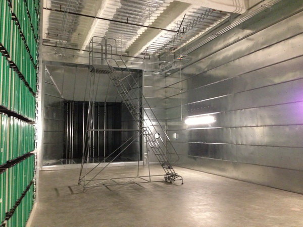
The plenum is large enough to drive a truck through.
 The Sutter Women’s and Children’s Hospital project in Sacramento, California, was headed for disaster in the preconstruction phase in 2009. The owner could see that the project was going to be hit with significant cost overruns and terminated the original construction team. SMACNA contractor Air Systems Service and Construction (ASSC) of Sacramento was part of the winning team when the project was rebid under an Integrated Project Delivery model.
ASSC, in a design-assist role, devised a huge 16-foot by 16-foot plenum served by the largest fan-wall system west of the Mississippi, along with engineer of record Capital Engineering. The contractor made good use of the services of SMACNA’s Technical Services Department to design ductwork that would deliver the constant-volume airflow required by the hospital, meet California’s stringent seismic requirements for hospitals and be economical to build.
Sutter Women’s and Children’s Hospital is a 395,241-square-foot building that includes a basement, eight floors of patient rooms and services including PICU, NICU, ICU; labor and delivery; and ante/postpartum, examination and isolation rooms.
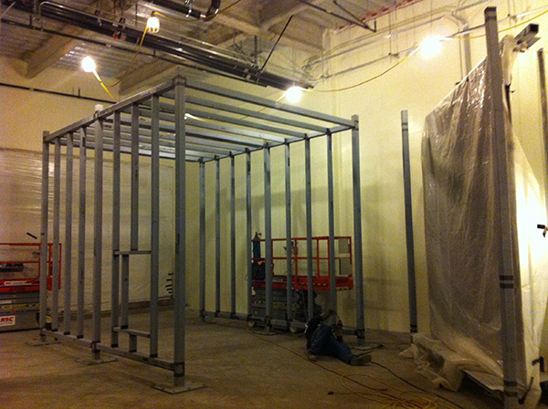
ASSC: The reinforcing exoskeleton.
The ninth-floor penthouse is a fully built up HVAC mechanical system consisting of 200 fan wall cubes with individual VFDs controlled by a central panel moving over 500,000 CFM. The plenum is pressurized to 6-inches of static pressure.
“The fan wall modulates as a whole to maintain designed static pressure in the system,” says Jim Meurer, executive vice president at ASSC. “As this is an acute care facility, the terminal units are CAV versus VAV. One of the benefits of the fan wall is its inherent redundancy. If a fan cube fails or needs repair, the rest of the fan cubes will ramp up to maintain system static.”
Heating and cooling are generated at, and supplied from, a separate central plant. The penthouse cooling section is composed of 24 129-inch by 51-inch chilled-water cooling coils that totaled 2,640 GPM. The campus central plant also supplies space heat and domestic hot water from two steam exchanger systems.
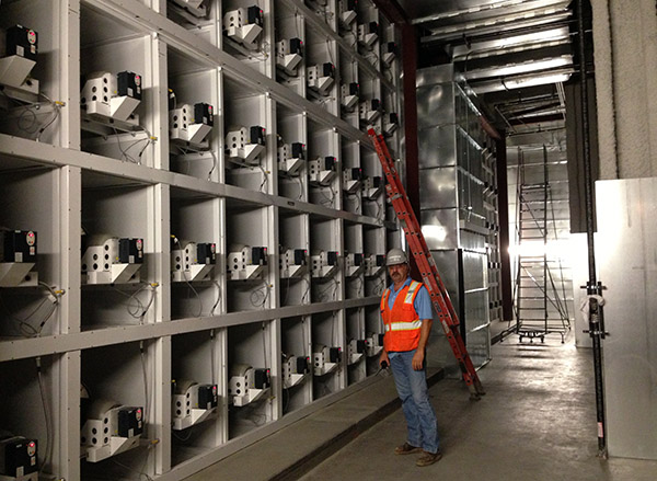
The large fan wall.
“The ninth floor of the building is dedicated primarily for a built-up mechanical penthouse air handler,” says Meurer. “It is a conventional system, but is on a massive scale. This single penthouse system effectively serves the entire building.”
So why create a plenum large enough to drive a truck through? It’s because of the laws of physics, says Mark Terzigni, SMACNA’s director, engineering and technical resources.
“The laws of physics require a certain amount of air at a certain temperature to heat or cool a space,” Terzigni explains. “Years ago, when first cost was the deciding factor, ductwork was smaller and air had to be delivered at higher pressures, which resulted in higher energy use. Now that life cycle costs trump first costs, ductwork is larger which allows fan horsepower to be lower.”
When he teaches a class, Terzigni points out that CFM equals velocity multiplied by the cross sectional area. As the cross sectional area gets bigger, energy costs get smaller because the fan horsepower goes down to deliver the same CFM.
The contractor and SMACNA’s Technical Services Department relied on both the HVAC Duct Construction Standards and the Rectangular Industrial Duct Construction Standards manuals to design the 16-foot by 16-foot plenum. The industrial manual is a design guide that allows the contractor to work out solutions for various conditions and specifications, based primarily on engineering theory that has been validated by actual construction projects.
Typically, ductwork comes off a coil line in sections, is joined together, and then it’s reinforced. The Sutter Hospital project reversed this sequence in order to meet static pressure and seismic bracing requirements. The contractor built the reinforcement first, an exoskeleton that was supported every 8-feet on center with 4-inch welded tube steel frames.
“Given the seismic criteria we were facing,” Meurer explains, “we came up with the concept of ‘bridging’ between the seismic support frames with additional 4-inch tube steel horizontal members, as well as adding 2-inch by 4-inch tube steel ribs.”
“This created the complete exoskeleton frame, which then allowed us to simply skin the interior with TDC plenum panels. The TDC plenum panels were joined with conventional duct flange gasketing, and sealed with high-pressure duct sealant. Once the system was completed, it was externally insulated,” he says.